Monday, May 2, 2011

Osama bin Laden spam invades Facebook

I guess the news about the death of Osama bin Laden is starting to reach everyone around the world. Every time something big as this happens, people get curious and start searching on the Internet.

Facebook ads are already spreading using videos of the death of Osama bin Laden as a trigger. On one Page we can see multiple users posting the same URL, with the following message:"Sweet! FREE Subway To Celebrate Osamas Death - 56 Left HURRY!" or "2 Southwest Plane Tickets for Free - 56 Left Hurry" and then a link to a short URL service (tiny.cc).


When you click the link, you will be redirected to a page, where it says that you need to post a message to get more instruction on how you can win.


If the user writes the message, it will post a new message on the user’s wall, to spread the message further, and then just redirect you to another page where you can win something else. The scheme of this scam is to keep redirecting you to pages where you have to enter information such as email, and eventually get money for all new users or clicks.


Please make sure that your computer is up to date with all the security patches, that your antivirus is updated and if you do click on the links from Facebook and other social media pages, make sure that you don’t give out any important information (username, passwords).

Since the bad guys seem to be taking advantage of this opportunity quite heavily, we expect to see more malicious code getting triggered by the death of Osama bin Laden.


Author: David Jacoby, Kaspersky Lab Expert.

Saturday, April 30, 2011

Real Time Mobile GPS Tracker with Google Maps

This project describes how you can build a mobile real time GPS tracker with integrated Google Maps. I began this project mainly to see if I can integrate all the different pieces of hardware and software to make a workable solution, and it took some time, but finally when everything was said and done, it looked pretty cool. I tore down everything and rebuilt it from scratch, making detailed notes and documenting the process.
When I started building this, I didn’t have any particular application in mind, but now that I have built it, I can see myself using it different applications, particularly if I can get to lower the cost. Even if you didn’t have any application in mind, it would be a fun weekend project, you never know, you might find the knowledge gathered during the process useful one day in some form or other.
How it works?

In a nutshell, this is how the GPS Tracker works. The GPS chip outputs the positioning information which is transferred over a GPRS link to the mobile operator’s GGSN (Gateway GPRS Support Node) and then to  a remote server over a TCP connection. The TCP server stores the incoming positional data in a mySQL database. When a user clicks on the tracking page, Zope, which is an open source web application server, serves up an HTML page with an embedded javascript code. The javascript would run in the user's browser and has instructions to retrieve the positional information from the mySQL database every second. It then integrates this information into Google Maps through Google Maps API which displays the position on a map. Since the positional information is retrieved every second and the maps updated at the same frequency, a real time GPS tracking effect is achieved. 


GPS Tracker2


GPS Tracker3


GPS Tracker


How much does it cost?


The costs are all associated with the hardware components. There is no software costs involved, since everything is open source.  The code is licensed under Creative Commons, so you’re free to use the code in this project in whatever applications you wish. I just ask that you acknowledge this site and also request you to drop me a comment with how you are using it.

The total estimated cost is around $200. All the components can be purchased from Sparkfun.


HARDWARE

The hardware consists of three main components.

Microcontroller

The micro-controller is the central controller for the whole unit. I chose the Arduino Duemilanove, which is an open source electronics prototyping board based on the Atmel ATMega328 8 bit micro-controller running at 16 Mhz.                                                                                                                                                         This newer version of this board can be purchased from here and costs around $30. It’s called Arduino Uno and works just as well.


GSM/GPRS Module


The GSM/GPRS Module is based on SpreadTrum's SM5100B. The SM5100B is a miniature, quad-band GSM 850/EGSM 900/DCS 1800/PCS 1900 module. This module features two UARTS, an SPI interface, and two 10-bit ADC's.  This board can be purchased from here and costs about $100.


GPS Module


The GPS Module is USGlobalSat EM-406A which is based on the spectacular SiRF Star III chipset. It outputs positioning and timing date in NMEA 0183 and SiRF binary protocol and has a positioning accuracy of 10 meters without and 5 meters with WAAS.  You have to buy a separate interface board and the GPS unit and connect the two. The interface board can be purchased from here and costs $16. The GPS receiver can be purchased from here and costs $ This unit can be purchased from here and costs $60.


 shield


HARDWARE ASSEMBLY

If you are using the hardware components I used, the assembly is pretty staightforward. Solder the Arduino stackable headers (can be bought from here) on the GPS shield and the GSM shield. Connect the GPS module to the GPS shield and stack it on top of the GSM board. Stack the two boards on top of the Arduino board.
SONY DSC

gps1


SOFTWARE


ARDUINO CODE

This is the code for the ATMega328P microcontroller on the Arduino board. Follow the directions at http://www.arduino.cc/ on how to compile and load the code onto the Arduino board. The code uses additional libraries.  They are:
  • NewSoftSerial

  • TinyGPS

  • PString

All 3 libraries can be downloaded from http://arduiniana.org/libraries/. Follow the instructions to install them.

The following should be noted:
The line: cell.println("AT+CGDCONT=1,\"IP\",\"isp.cingular\"");establishes a PDP (Packet Data Protocol) context with AT&T's APN (Access Point Name). If your cellular provider is not AT&T, replace the string "isp.cingular" with the appropriate APN for your cellular provider. In the line: cell.println("AT+SDATACONF=1,\"TCP\",\"your_ip_address\",32000"); Change this to the IP Address for your TCP Server.

//Include the NewSoftSerial library to send serial commands to the cellular module.
 
 
#include  
 
#include 
#include 
 
#define POWERPIN 4
#define GPSRATE 4800
#define BUFFSIZ 90
 
char at_buffer[BUFFSIZ];
char buffidx;
 
 
int firstTimeInLoop = 1;
 
int GPRS_registered;
int GPRS_AT_ready;
 
 
//Will hold the incoming character from the Serial Port.
char incoming_char=0;      
char buffer[60];
 
 
PString myString(buffer,sizeof(buffer));
//Create a 'fake' serial port. Pin 2 is the Rx pin, pin 3 is the Tx pin.
NewSoftSerial cell(2,3);  
TinyGPS gps;
 
 
int redLedPin  = 11;
int blueLedPin = 12;
 
// Function to Blink a LED
// Parameters: lPin   - Pin of the LED
//             nBlink - Number of Times to Blink
//             msec   - Time in milliseconds between each blink
 
void blinkLed(int lPin, int nBlink, int msec) {
 
if (nBlink) {
for (int i = 0; i < nBlink; i++) {
digitalWrite(lPin, HIGH);
delay(msec);
digitalWrite(lPin, LOW);
delay(msec);
}
}
}
 
// Function to Switch on a LED 
// Parameters: lPin - Pin of the LED
 
void onLed (int lPin) {
digitalWrite(lPin, HIGH);
}
 
 
// Function to Switch off a LED
// Parameters: lPin - Pin of the LED
 
void offLed (int lPin) {
digitalWrite(lPin, LOW);
}
 
 
// Do system wide initialization here in this function
void setup()
{
 
// LED Pin are outputs. Switch the mode 
 
pinMode(redLedPin, OUTPUT);
pinMode(blueLedPin, OUTPUT);
 
 
/* Blink the Power LED */
blinkLed(redLedPin,3,500);
 
//Initialize serial ports for communication.
 
Serial.begin(4800);
cell.begin(9600);
//Let's get started!
 
Serial.println("Starting SM5100B Communication...");
 
delay(5000);
 
/* Currently GPRS is not registered and AT is not ready */
 
GPRS_registered = 0;
GPRS_AT_ready = 0;
 
 
}
 
/* Reads AT String from the SM5100B GSM/GPRS Module */
 
void readATString(void) {
 
char c;
buffidx= 0; // start at begninning
while (1) {
if(cell.available() > 0) {
c=cell.read();
if (c == -1) {
at_buffer[buffidx] = '\0';
return;
}
 
if (c == '\n') {
continue;
 
}
 
if ((buffidx == BUFFSIZ - 1) || (c == '\r')){
at_buffer[buffidx] = '\0';
return;
}
 
at_buffer[buffidx++]= c;
}
}
}
 
 
/* Processes the AT String to determine if GPRS is registered and AT is ready */
 
void ProcessATString() {
 
if( strstr(at_buffer, "+SIND: 8") != 0 ) {
GPRS_registered = 0;
Serial.println("GPRS Network Not Available");
}
 
if( strstr(at_buffer, "+SIND: 11") != 0 ) {
GPRS_registered=1;
Serial.println("GPRS Registered");
blinkLed(redLedPin,5,100);
 
}
 
if( strstr(at_buffer, "+SIND: 4") != 0 ) {
GPRS_AT_ready=1;
Serial.println("GPRS AT Ready");
}
 
}
 
 
void loop() {
 
/* If called for the first time, loop until GPRS and AT is ready */
 
if(firstTimeInLoop) {
firstTimeInLoop = 0;
while (GPRS_registered == 0 || GPRS_AT_ready == 0) {
readATString();
ProcessATString();
 
}
 
if(POWERPIN) {
pinMode(POWERPIN, OUTPUT);
}
 
pinMode(13, OUTPUT);
 
Serial.println("GPS Parser Initialized");
digitalWrite(POWERPIN, LOW);
delay(1000);
Serial.println("Setting up PDP Context");
cell.println("AT+CGDCONT=1,\"IP\",\"isp.cingular\"");
delay(1000);
Serial.println("Activating PDP Context");
cell.println("AT+CGACT=1,1");
delay(1000);
Serial.println("Configuring TCP connection to TCP Server");
cell.println("AT+SDATACONF=1,\"TCP\",\"\",");
delay(1000);
Serial.println("Starting TCP Connection\n");
cell.println("AT+SDATASTART=1,1");
 
onLed(redLedPin);
 
} else {
 
while(Serial.available()) {
int c = Serial.read();
if (gps.encode(c)) {
onLed(blueLedPin);
float flat, flon;
unsigned long fix_age;
gps.f_get_position(&flat,&flon,&fix_age);
if(fix_age == TinyGPS::GPS_INVALID_AGE)
Serial.println("No fix detected");
else if (fix_age > 5000)
Serial.println("WARNING: Possible Stale Data!");
else {
myString.print("AT+SSTRSEND=1,\"");
myString.print("Lat: ");
myString.print(flat,DEC);
myString.print(" Long: ");
myString.print(flon,DEC);
myString.print("\"");
Serial.println(myString);
cell.println(myString);
myString.begin();
offLed(blueLedPin);
}
}
 
}
 
}
 
}
 

TCP SERVER


The TCP Server is coded in python. It’s very simple in operation, basically opens up a TCP port and waits for the connection from the GPS Tracker’s GSM module. Once it receives, the connection, it accepts it and as and when the GPS packets comes, in it parses it out and stores the Latitude and Longitude in a MySQL table (which we’ll be creating in the next section). The TCP server will run on any python 2.x, download it from http://www.python.org/. It’s worth noting that Python 3 has major syntax changes, therefore the code will not run until you tweak it to make it compatible with Python 3. It uses a python library called MySQLdb, which you can download from MySQLdb from http://www.zope.org/Members/adustman/Products/MySQLdb . Follow the instructions to install it onto your python installation.

Type the following code into a file called tcpServer.py and you can run it by typing python tcpServer.py on the command prompt.  Replace ‘your_ip_address’ with the IP Address of the machine you’re running the TCP Server on. Note that if your machine in on the LAN and you have a router/firewall, you might have to port forward TCP port 32000 to the IP Address of the machine on which the TCP Server is running. Otherwise, packets coming in from outside your network will never reach the TCP Server machine. Don’t run the server code now, we still have lots of coding to do. Save the file and move on to the next section.

Also note that, you don’t have to use TCP. You can also use UDP or any other transport protocol. TCP packets have a 20 byte header whereas UDP has only 8 bytes. TCP also is a complex protocol and is an overkill for this application. I used it, but feel free to use UDP.
 
#!/usr/bin/env python
 
import socket
import MySQLdb
 
TCP_IP = ‘your_ip_address"’
TCP_PORT = 32000
BUFFER_SIZE = 40
 
# ClearDB. Deletes the entire tracking table
 
def ClearDB(curs,d ):
curs.execute ("""
INSERT INTO gmaptracker (lat, lon)
VALUES (0.0,0.0)""")
d.commit()
 
 
# Connect to the mySQL Database
 
def tServer():
try:
 
db = MySQLdb.connect (host = "your_host",
user = "your_user",
passwd = "your_password",
db = "gmap" )
except MySQLdb.Error, e:
print "Error %d: %s" %(e.args[0], e.args[1])
sys.exit(1);
 
cursor = db.cursor()
 
# Start with a fresh tracking table
 
ClearDB(cursor,db)
 
# Set up listening Socket
 
try:
s = socket.socket(socket.AF_INET, socket.SOCK_STREAM)
s.setsockopt(socket.SOL_SOCKET, socket.SO_REUSEADDR, 1)
s.bind((TCP_IP, TCP_PORT))
print "Listening...."
s.listen(1)
conn, addr = s.accept()
print 'Accepted connection from address:', addr
 
except socket.error:
if s:
s.close()
print "Could not open socket: "
cursor.close()
conn.close()
db.close()
sys.exit(1)
 
 
try:
while 1:
data = conn.recv(BUFFER_SIZE)
if not data:break
 
str1,str2 = data.split("Long: ")
str1 = str1.split("Lat: ")[1]
latitude = float(str1)
longitude = float(str2)
cursor.execute ("""
INSERT INTO gmaptracker (lat, lon)
VALUES (%s,%s)""", (latitude,longitude))
 
db.commit()
 
except KeyboardInterrupt:
ClearDB(cursor,db);
cursor.close()
conn.close()
db.close()
 
 
if __name__ == '__main__':
tServer()


MYSQL

A MySQL database is used to store the GPS Co-ordinates received. If you are using Ubuntu, as I did, you can use the apt-get utility to download and install the MySQL server as follows. I used Version 5.1 of MySQL server.
sudo apt-get install mysql-server-5.1
The Installer will ask for a root password. Enter your root password. This will be needed to log on to the MySQL database later as root.
You also need the development (header) files of the MySQL client. You can install it by entering:
sudo apt-get install libmysqlclient-dev
Now, we’ll setup the MySQL database. First log on using the username and password you set earlier. Enter
mysql -p -u user
Enter the root password when prompted.
It’s usually not a good idea to work on a MySQL database as root, so we’ll make another user, grant all privileges and than we’ll use that to make further changes. The mysql prompt is shown below as mysql>. Replace user, host and password with your values. If the mySQL database is on the same machine, you can enter ‘localhost’ for ‘host’. For example, jayesh@’localhost’.
msql> GRANT ALL PRIVILEGES ON *.* TO user@'host' IDENTIFIED BY 'password';
Let’s now create a database. We’ll call it gmap.  Enter:
mysql> CREATE DATABASE gmap;
Now, we can see if the database has been created, by entering:
mysql> show databases;
You should see something like this:


Database
information_schema
gmap
mysql
The table shows the current databases in MySQL. The other entries might be different in your system, but as long as you have the gmap database, you’re doing fine so far.
Next change to the gmap database by entering:
mysql> use gmap;
Let’s now create a table to hold our lat/long in the gmap database we created.
mysql> CREATE TABLE gmaptracker (
-> id int(8) NOT NULL auto_increment,          
-> lat double(13,10) NOT NULL default 0.0000000000,
-> lon double(13,10) NOT NULL default 0.0000000000,
-> PRIMARY KEY (id)          
-> ) TYPE=InnoDB;
The table we created can be viewed by entering:
mysql> show tables;
The output will show the table we just created.


Tables_in_gmap
gmaptracker
If you want to see the fields in the gmaptracker table, enter:
mysql> desc gmaptracker;
The output will show the fields in the table gmaptracker which we created.


FieldTypeNullKeyDefaultExtra
idint(8)NOPRINULLauto_increment
latdouble(13,10)NO0.0000000000
londouble(13,10)NO0.0000000000

Finally, since the table is now empty, when we issue:
mysql> select * from gmaptracker;
it should show:
Empty set
Congratulations! You have a working MySQL database and a table in it ready to accept the GPS co-ordinates.

PLONE

The next piece of software we need to install is Plone. Plone is a CMS (Content Management System) built on top of Zope, which is a popular web application server. We’ll be using only the Zope functionality of Plone and not it’s CMS features. In fact, using Plone for this application is an overkill since you can just download Zope and use that. I already had Plone installed on my computer and I’ll show you how to use Plone, but if you want to try Zope, you’re welcome to do that. The steps are very similar.
cd /usr/local/src sudo tar -xvf Plone-3.3.5-UnifiedInstaller.tgz cd Plone-3.3.5-UnifiedInstaller/ sudo ./install.sh standalone
  • Note down the Username and Password displayed at the end of the installation process. You'll need it to access the Plone GUI. Plone will be installed in /usr/local/Plone

Go to the Zope Directory in Plone, in this case it's /usr/local/Plone/Zope-2.10.11-final-py2.4.
Download ZmySQLDA from http://www.zope.org/Members/adustman/Products/ZMySQLDA into that directory and extract the tar file with the command:
sudo tar -xvxf ZMySQLDA-2.0.8.tar.gz
If everything goes ok, a ZMySQLDA directory will be created under /usr/local/Plone/Zope-2.10.11-final-py2.4/lib/python/Products.
ZMySQLDA is a SQL Database Adaptor that Zope will be using to talk to the database. ZMySQLDA using another piece of software called MySQLdb to perform it’s tasks. Let’s download and install MySQLdb now.
cd /usr/local/Plone/Zope-2.10.11-final-py2.4/lib/python/Products
Download MySQLdb from http://www.zope.org/Members/adustman/Products/MySQLdb into that directory
Extract the tarball and install MySQLdb with the following commands:
sudo tar -xvf MySQL-python-1.2.0.tar.gz
cd MySQL-python-1.2.0
sudo /usr/local/Plone/Python-2.4/bin/python setup.py build sudo /usr/local/Plone/Python-2.4/bin/python setup.py install
One very important thing to note when building and installing MySQLdb is to use the same python binary that was shipped with Plone. If you don’t use the same exact python binary that was shipped with Plone, Plone won’t be able to find it. In this case the python binary that was shipped with Plone resides in /usr/local/Plone/Python-2.4/bin.
Start Plone
cd /usr/local/Plone/zinstance/bin sudo ./plonectl start
Wait for a few moments for Plone to start up and then open a browser and point it to: http://localhost:8080/manage_main. This is assuming everything is on the same computer. If you are accessing from a different computer, change localhost to the IP Address of the computer running Plone.
You should see a dialog box for entering the username and password. Enter the username and password you noted down after the Plone installation process.  You should see the root folder view as shown below:
rootFolder
1. Create a SQL Database Connection
Select the 'Z SQL Database Connecton' from the drop down list on the right. In the database connection string text box, enter gmap@host:port. Replace host and port with your hostname and port respecively. If the SQL database is running on the same machine as Plone, enter
gmap   

Click the Browse tab of the Z MySQL Database Connection. You should be able to see your table (gmaptracker). Click the + sign and you should be able to see the elements of the table.
database
2. Add a Z SQL Method to retrieve the last row from the SQL table.
Select the 'Z SQL Method' from the drop down list on the right. Enter "GmaplocsPkSelectLastAdded" for id and "SQL Method to select Data" for tile.
Enter the code:
select * from gmaptracker order by id desc limit 1

Click Add.
From the root folder view, Click the GmaplocsPkSelectLastAdded method from the root folder view and click the Advanced Tab. Change the value of "Maximum rows to retrieve" to 0 (zero). Save the changes.
reducerows
On why this should be done, read this. http://www.zope.org/Members/adustman/Tips/no_limits
3. Add a DTML Method
Go to the root folder view. Select the 'DTML Method' from the drop down list on the right. Enter "data.xml" for id and an descriptive title (can by anything you want). Click Add and Edit.
Enter the code
xml version="1.0" encoding="UTF-8"?>
<markers>
<dtml-in GmaplocsPkSelectLastAdded>
<marker lat="&lt;dtml-var lat>" lng="<dtml-var lon>"/>
dtml-in>
markers>

Save the changes.
4. Add a DTML Document
Go to the root folder view. Select the 'DTML Document' from the drop down list on the right'. Enter "gpstrack.html" for id and a descriptive name. Click Add and Edit.
Enter the code:
DOCTYPE html PUBLIC "-//W3C//DTD XHTML 1.0 Strict//EN" 
"http://www.w3.org/TR/xhtml1/DTD/xhtml1-strict.dtd">
<html xmlns="http://www.w3.org/1999/xhtml">
<head>
<title>Real Time GPRS based GPS Trackertitle>
<script src="http://maps.google.com/maps?
file=api&v=1" type="text/javascript">script>


Make your own motion sensor alarm with SMS feature

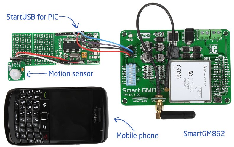
MikroEleketronika demonstrates how to build a simple home alarm system that has the capability of sending SMS to a predefined cell phone number when intrusion is detected. This project is based on StartUSB for PIC board, a small development board for PIC18F2550, which is preprogrammed with an USB bootloder so that no additional programmer is required to load the firmware. The SMS portion uses a SmartGM862 Board, which is a full-featured development tool for the Telit’s GM862 GSM/GPRS module. All the boards required for this project can be purchased as SMS Home Alarm Kit from mikroElektronika. A demonstration software for PIC is also available for free. They are offering free shipping now.

DIY home alarm kit

Asynchronous serial communication

The PIC16F628A microcontroller has a built in Universal Synchronous Asynchronous Receiver Transmitter (USART) hardware that allows to communicate with a wide range of serial devices such as memory chips, LCDs, personal computers, etc. The USART module has two modes of operation: synchronous (requires a synchronized clock between the transmitter and receiver) and asynchronous (no synchronization clock required). As the asynchronous mode is more popular, we will focus today’s lab session on this and will establish a two way serial data link between the PIC microcontroller and a PC.
Required Theory

Serial communications are used in microcontroller-based systems, mostly due to the scarcity of available I/O pins. Besides for long distance communications, serial data transfer is more simple and cost effective as the required hardware connections in the data link can be reduced to three (Tx, Rx, and Gnd).

There are two different types of serial communications: synchronous and asynchronous. The key challenge in a serial data link is to maintain the synchronization between the transmitter and the receiver. The asynchronous method uses a start and stop bit protocol to synchronize the two ends. Each character byte is sent in a frame consisting of a start bit , followed by the character bits, followed (optionally) by a parity bit, and finalized by one or more stop bits. The sender and receiver have to be initialized to use the same data rate, number of data bits, and number of stop bits.
In idle condition, the transmit output is at logic high. When the transmitter is ready to send a character byte, it signals the receiver by pulling the transmit line low for one clock period. This is the start bit and it tells the receiver that a frame follows. The receiver reads the number of character bits expected according to the adopted protocol until the line is pulled to logic high by the transmitter (one or more stop bits), and that is the end of the frame. The whole process is repeated every time the transmitter has to send a character byte. This form of serial transmission is called asynchronous because the receiver resynchronizes itself to the transmitter every time the data is sent using the start bit. However, within each frame the two parties are synchronized.
On the other hand, the synchronous serial communication transmit characters in blocks with no framing bits surrounding them. The transmitter and receiver are synchronized with a separate clock line or, in some cases, the clock signal is contained in the transmitted characters. In both the types of serial communications, the rate at which the data is sent and received is known as the baud rate.
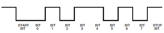
The USART module inside the PIC16F628A microcontroller supports both types of serial communications but it is best suited for the asynchronous method. In asynchronous mode, RB2 acts as a data transmit (TX) output, and RB1 as data receive (RX) input. A byte of serial data is sent as a string of 10 bits; a start bit, eight data bits, and a stop bit, as shown below.
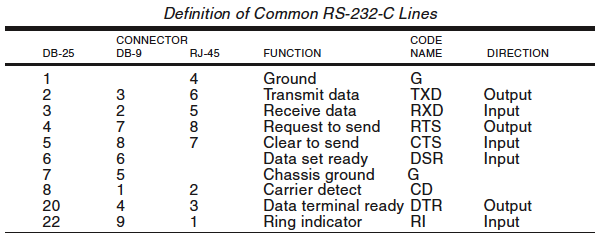
The PC’s serial port (also known as COM port) uses the RS232-C standard for serial communication. This standard specifies the electrical, mechanical, functional signal and procedural specifications of the serial communication interface. A logic high for RS232-C is a signal voltage in the range of -3 V to -15 V (typically -12 V), and a logic low is between +3 V to +15 V (typically +12 V). So unlike the PIC microcontroller’s logic levels, an RS232-C high is a negative voltage, and a low is a positive voltage. The table below shows the standard connections for RS232-C, for 25-pin, 9-pin and RJ-45 connectors. For details on each of these signal pins, you can find tons of literature online. For this experiment, we are implementing a minimal serial interface between the PIC microcontroller and a PC by using only the TX, RX, and GND signals.

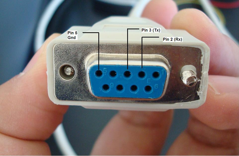
RS232 signal pins in a DB-9 female connector
We are going to use asynchronous mode to communicate with an RS232-C serial port on the PC. Since the PIC16F628A already has a built in hardware (USART) that supports asynchronous serial communication, so all that is required is an external level shifter to translate TTL signals from PIC to RS232-C levels, and vice-versa. This can be achieved by using a MAX232 chip made by Maxim. The chip requires a few external capacitors for its internal charge pumps to generate +12 V and -12 V required for the RS232-C communication. A simple way to send and receive bytes through the PC’s serial port is by using the application named HyperTerminal that comes with Windows operating system. You can open the HyperTerminal application window through Start → Menu → Programs → Accessories → Communications→ Hyperterminal. You can create a connection with your serial port (e.g. COM1), choose a baud rate, number of bits, parity setting, etc. When HyperTerminal connects to the serial port, whatever character you type is sent (as ASCII) through the serial port. The received characters are also displayed on the screen.
Circuit Setup
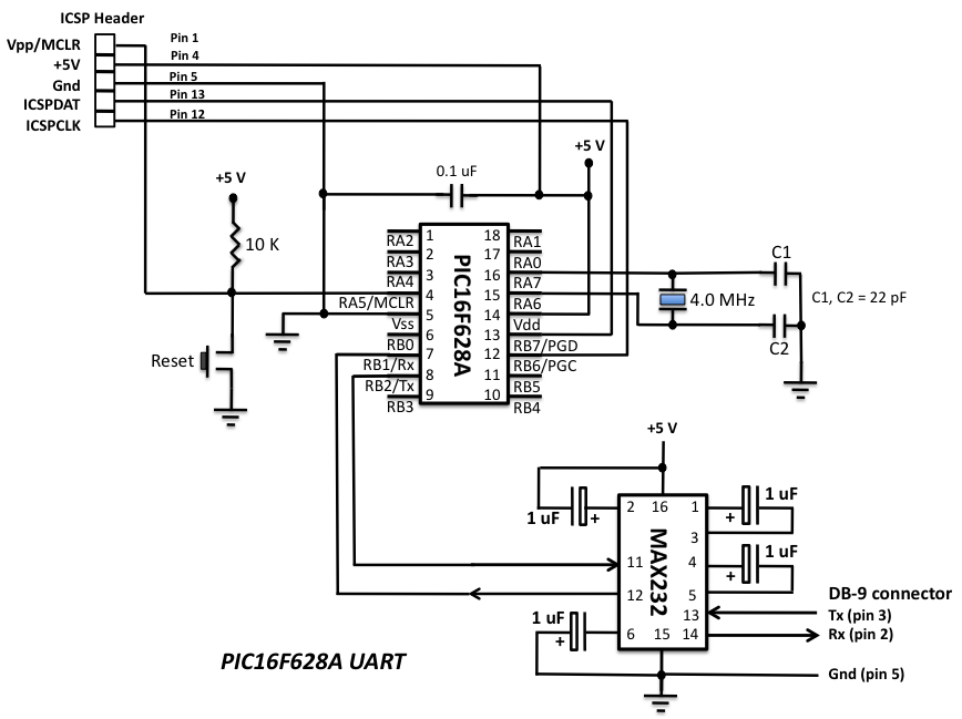
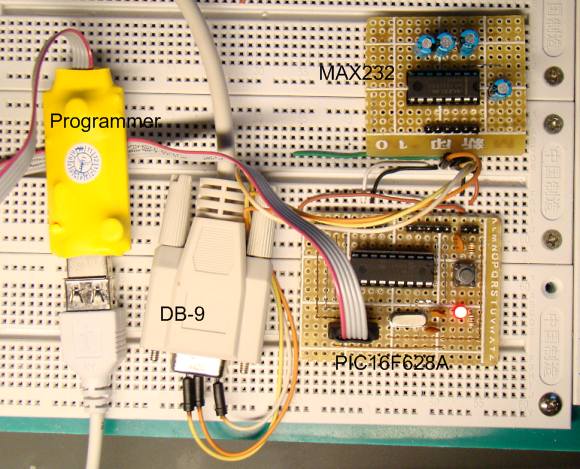
The circuit setup for this experiment is shown below. It has the basic setup circuit from PIC16F628A breadboard module and a level shfter using MAX232 chip. The MAX232 requires four external capacitors (each 1 uF) for its internal charge pumps. A MAX232 is actually a dual driver/receiver and we are just using one. For more details on the MAX232 chip, read the datasheet. On PC’s side, only three lines are connected (Tx, Rx, and Ground) to the COM port through a 9-pin connector.
Software
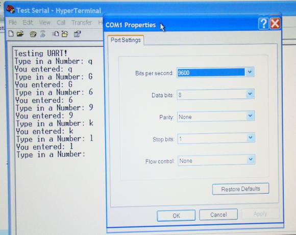
As usual, the program is developed with the MikroC Pro for PIC compiler. The MikroC compiler provides UART library that supports asynchronous serial communication in full duplex mode (that means transmit and receive simultaneously). This makes the programming lot easier. For example, if you want to initialize the hardware UART module of PIC16F628A with the data rate of 9600 baud, you just need to write UART1_Init(9600). The example code given here establishes a two way asynchronous serial link between the PIC16F628A microcontroller and the PC. The microcontroller sends the message ‘Type in a Number’ that is displayed on the Hyperterminal window. When you enter any character from the keyboard, it will be sent to the microcontroller through the COM port. The PIC microcontroller will read it and send it back to the PC, which will be again displayed on the Hyperterminal window. The Hyperterminal setttings for this should be
Bits per second: 9600, Data Bits: 8, Parity: None, Stop bits: 1, Flow control: None.

/*

Lab 8: Hardware UART

MCU: PIC16F628A

External 4MHz Crystal, MCLR Enabled, PWRT Enabled, WDT OFF

Copyright @ Rajendra Bhatt

Dec 12, 2010

*/


void newline(){

UART1_Write(13); // Carriage Return

UART1_Write(10); // Line Feed

}


void main() {

unsigned char MyError, Temp;

CMCON = 7; // Disable Comparators

TRISB = 0b00000010;

UART1_Init(9600);

Delay_ms(100);

UART1_Write_Text("Testing UART! ");

newline();


do {

UART1_Write_Text("Type in a Number: ");

while(!UART1_Data_Ready());

Temp = UART1_Read();

newline();

UART1_Write_Text("You entered: ");

UART1_Write(Temp);

newline();

} while(1);

} // End main()
Output
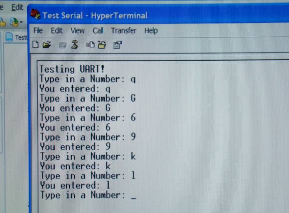
Here’s a snapshot of the output from the Hyperterminal window on my Windows XP machine. In order to display what you typed you need to turn on the ‘Echo typed character locally’ option on the settings.

Lab 12: Basics of LED dot matrix display

We covered how to interface seven segment LED displays to a PIC microcontroller in two sections: Lab 6 and Lab 11. Today, we will move on to interfacing an LED dot matrix display. LED dot matrices are very popular means of displaying information as it allows both static and animated text and images. Perhaps, you have encountered them at gas stations displaying the gas prices, or in the public places and alongside highways, displaying advertisements on large dot matrix panels. In this experiment, we will discuss about the basic structure of a monochrome (single color) LED dot matrix and its interface with a microcontroller to display static characters and symbols. We will cover the animation stuff in next tutorial. I am using the PIC18F2550 microcontroller on the StartUSB for PIC board for demonstration, but this technique is applicable to any other microcontrollers that have sufficient I/O pins to drive the LED matrix.


Interfacing a LED dot matrix display with a PIC microcontroller
Theory of LED dot matrix display
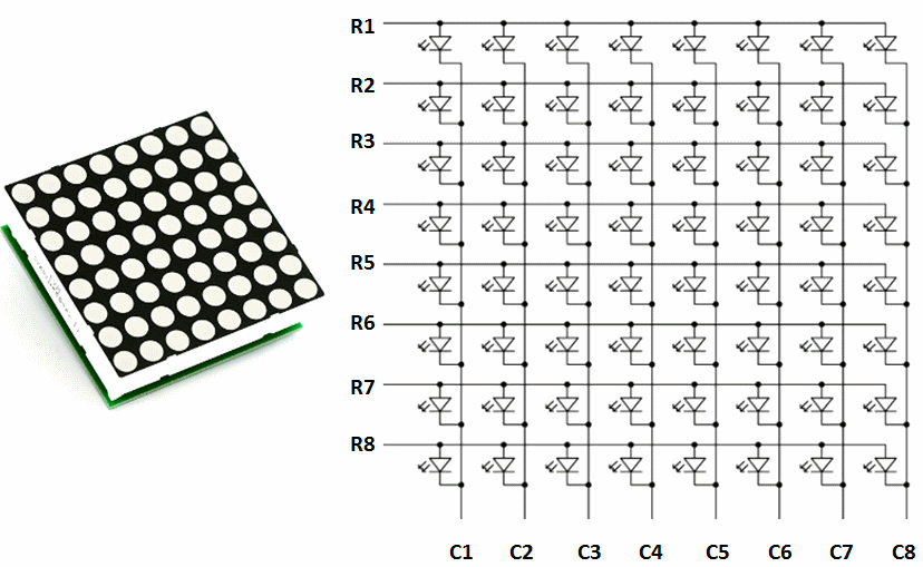
In a dot matrix display, multiple LEDs are wired together in rows and columns. This is done to minimize the number of pins required to drive them. For example, a 8×8 matrix of LEDs (shown below) would need 64 I/O pins, one for each LED pixel. By wiring all the anodes together in rows (R1 through R8), and cathodes in columns (C1 through C8), the required number of I/O pins is reduced to 16. Each LED is addressed by its row and column number. In the figure below, if R4 is pulled high and C3 is pulled low, the LED in fourth row and third column will be turned on. Characters can be displayed by fast scanning of either rows or columns. This tutorial will discuss the method of column scanning.

Structure of a 8x8 LED dot matrix
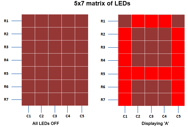
The LED matrix used in this experiment is of size 5×7. We will learn how to display still characters in a standard 5×7 pixel format. The figure below shows which LEDs are to be turned on to display the English alphabet ‘A’. The 7 rows and 5 columns are controlled through the microcontroller pins. Now, lets see in detail how it works.
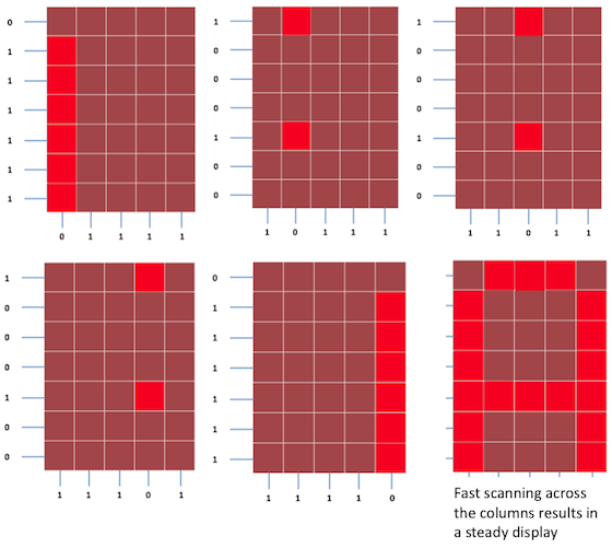
Suppose, we want to display the alphabet A. We will first select the column C1 (which means C1 is pulled low in this case), and deselect other columns by blocking their ground paths (one way of doing that is by pulling C2 through C5 pins to logic high). Now, the first column is active, and you need to turn on the LEDs in the rows R2 through R7 of this column, which can be done by applying forward bias voltages to these rows. Next, select the column C2 (and deselect all other columns), and apply forward bias to R1 and R5, and so on. Therefore, by scanning across the column quickly (> 100 times per second), and turning on the respective LEDs in each row of that column, the persistence of vision comes in to play, and we perceive the display image as still.

A standard 5x7 LED dot matrix display structure
The table below gives the logic levels to be applied to R1 through R7 for each of the columns in order to display the alphabet ‘A’.

Row values for displaying the alphabet A

Scanning across the columns and feeding with appropriate row values
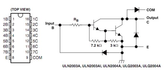
You should have noted that across each row, one pin is sourcing the current for only one LED at a time, but a column pin may have to sink the currents from more than one LED. For example, the column C1 should be able to sink the currents from 6 LEDs while displaying the alphabet ‘A’. A microcontroller’s I/O pin cannot sink this much of current, so external transistor arrays are required. I am using ULN2003A IC which has seven built-in Darlington transistor arrays (see below). The inputs of ULN2003A are active high. This means the input pins must be supplied with logic high in order to bring the corresponding output pins to ground. The schematic of the Darlington transistor array inside the ULN2003A chip is shown below.

Pin diagram and schematic of ULN2003A (Darlington transistor arrays)
Circuit Setup
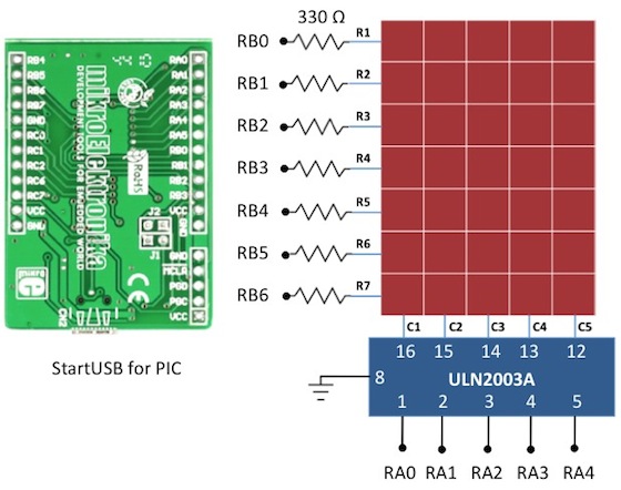
The circuit setup for this experiment is quite simple. You need seven 330 Ω resistors in series with rows R1 through R7 to limit the current through the LEDs. Then the rows are driven by RB0 through RB6 pins of PIC18F2550. The columns are connected to the five outputs of ULN2003A. The corresponding five input pins of ULN2003A IC are controlled by RA0 through RA4 pins of PIC18F2550. The microcontroller will, therefore, scan across the column by sending appropriate bits to PORTA. For example, setting RA0 to 1 and clearing RA1 through RA4 bits, will select the first column. The microcontroller will wait for about 1 ms before switching to the next column. At each column, the microcontroller will output the corresponding row value at PORTB to turn on the appropriate LEDs in the column that are required to display the specific character. The switching between columns is fast enough to deceive the human eyes and a steady character is displayed.
.
Circuit diagram for interfacing a 5x7 LED dot matrix with PIC18F2550

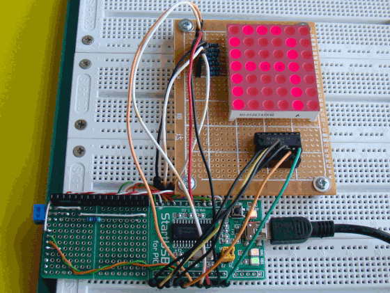
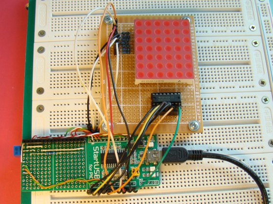
Circuit setup showing a StartUSB board with a 6x7 LED dot matrix (the sixth column is discarded here)
Software
The major part of this experiment is the software routine to scan the columns and feed the rows with appropriate values. The column-specific row values for display characters can be either defined in RAM or stored in the program memory in case the on-board RAM is not sufficient enough. In mikroC, the variables are saved in RAM and constants are stored in program memory. So, if your PIC does not have enough RAM, you can define a constant array to store the row values so that a part of the program memory is occupied by it to free up the on-board RAM. PIC18F2550 has quite a bit of RAM (2 KB), so I have used RAM to store the row values for alphabets A through Z. Here’s how I define it in mikroC,
unsigned short Alphabets[130]={ 0x7e, 0×09, 0×09, 0×09, 0x7e, // A
0x7f, 0×49, 0×49, 0×49, 0×36,  // B
0x3e, 0×41, 0×41, 0×41, 0×22,
0x7f, 0×41, 0×41,0×22, 0x1c,
0x7f, 0×49, 0×49, 0×49, 0×63,
0x7f, 0×09, 0×09, 0×09, 0×01,
0x3e, 0×41, 0×41, 0×49, 0x7a,
0x7f, 0×08, 0×08, 0×08, 0x7f,
0×00, 0×41, 0x7f, 0×41, 0×00,  // I
0×20, 0×40, 0×41, 0x3f, 0×01,
0x7f, 0×08, 0×14, 0×22, 0×41,
0x7f, 0×40, 0×40, 0×40, 0×60,
0x7f, 0×02, 0×04, 0×02, 0x7f,
0x7f, 0×04, 0×08, 0×10, 0x7f,
0x3e, 0×41, 0×41, 0×41, 0x3e,
0x7f, 0×09, 0×09, 0×09, 0×06,
0x3e, 0×41, 0×51, 0×21, 0x5e,
0x7f, 0×09, 0×19, 0×29, 0×46,
0×46, 0×49, 0×49, 0×49, 0×31,  // S
0×01, 0×01, 0x7f, 0×01, 0×01,
0x3f, 0×40, 0×40, 0×40, 0x3f,
0x1f, 0×20, 0×40, 0×20, 0x1f,
0x3f, 0×40, 0×30, 0×40, 0x3f,
0×63, 0×14, 0×08, 0×14, 0×63,
0×07, 0×08, 0×70, 0×08, 0×07,
0×61, 0×51, 0×49, 0×45, 0×43 // Z
};
And this is how mikroC allows you to store arrays in the program memory.
const unsigned short characters[30]={
0×24, 0x2A, 0x7f, 0x2A, 0×12, // $
0×08, 0×14, 0×22, 0×41, 0×00, // <
0×41, 0×22, 0×14, 0×08, 0×00, // >
0×14, 0×14, 0×14, 0×14, 0×14, // =
0×36, 0×49, 0×55, 0×22, 0×50, // &
0×44, 0x3c, 0×04, 0x7c, 0×44, // PI
};
I have written a simple program in mikroC to display the alphabets A through Z sequentially, and some special characters too. You can watch the video below to see how they look like on the dot matrix display.
Download mikroC project files

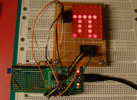
Displaying symbol PI

Friday, April 29, 2011

DSL Reports intrusion compromises over 9000 accounts

DSL Reports - the information and review site on high speed Internet services which operates over 200 forums - has been hit with a blind SQL injection attack, which resulted in the compromise of at least 9000 accounts.

Founder Justin Beech posted a notification about the intrusion on the forum dedicated to the site, in which he specified that no login names, zip codes and private posts were compromised.

The attack went on for four hours on Wednesday and it was blocked before it had completed more than 8% of its work. All the same, the attackers managed to obtain a large number of email/password pairs.

"The ones they obtained were basically random. So they cover the entire 10 year history of the membership but sprinkled randomly. Some are very old accounts, some are new accounts, some inactive or deleted," says Beech.

"I identified the newest accounts, those that were obtained and have logged in over the last 12 months, and have alerted those by email. Older inactive accounts involved are also being notified by email now, although the older the account, the less likely the email is still current, or the password they used is still useful."

Once the intrusion was detected, stopped and the extent of the compromised accounts has been discovered, passwords for those accounts have been reset. Beech urges the users who received the notification to change their password and to do the same on accounts for other sites (Gmail, PayPal, Facebook, etc.) on which they used the same email/password combination.

"Obviously having both an sql injection attack hole (now closed) and plain text passwords is a big black eye, and I'll be addressing these problems as fast, but as carefully, as I can," promises Beech. 

PSN hackers claim to have 2+ million credit card numbers

The PlayStation Network hack is now considered to be one among the biggest data thefts of all time, and according to the claims made by the alleged hackers on underground Internet forums, it seems that some 2.2 million credit card numbers were, indeed, stolen.


Security researchers have been sifting through the hacker forums and say that there has been talk of the hackers contacting Sony in order to sell back the credit card list to the company for $100,000, but that Sony didn't respond to the offer.

Whether the claims are true or not it is impossible to tell. "The entire credit card table was encrypted and we have no evidence that credit card data was taken, said Sony. "The personal data table, which is a separate data set, was not encrypted, but was, of course, behind a very sophisticated security system that was breached in a malicious attack."

“Sony is saying the credit cards were encrypted, but we are hearing that the hackers made it into the main database, which would have given them access to everything, including credit card numbers,”said security consultant Mathew Solnik for The New York Times.

Also, even if the data is encrypted, it doesn't mean that it can't be decrypted by the attackers, and Sony didn't offer any details about the encryption method used. Although, if the hackers managed to break it, I doubt they would be trying to sell the list back to Sony. On the other hand, they could always sell it to other criminals who know how do it.

Sony has advised PS users to keep a close eye on their financial statements in order to spot a fraudulent transaction as soon as it happens.